Introduction to Radio Navigation for Cross-Country flight
Radio and Area Navigation
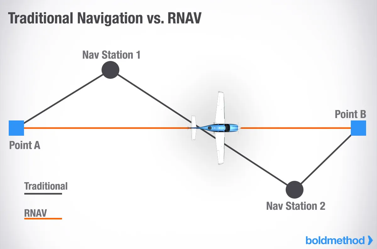
Radio and Area navigation are two distinct types of navigating in aviation.
- Radio navigation is a method of navigation that utilizes ground-based navigational aids (nav aids) to determine an aircraft's speed, position and track.
- Area navigation (RNAV) is a method of navigation that allows an aircraft to fly on any desired fliht path within the coverage of ground- or space-based nav aids, rather than being restricted to specific, fixed ground-based radio beacons.
VHF Omnidirectional Range (VOR)
Very High Frequency Omnidirectional Range, or VOR, is a navigational aid that consists of a ground-based sender (the VOR itself) and an airborne receiver that sits in the aircraft. It utilizes phase-shifting to determine an aircraft's position in regards to the VOR.
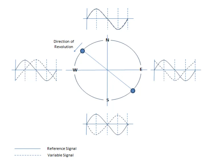
The frequency range of a VOR is between 108.0 MHz and 117.95 MHz. Every VOR is oriented to magnetic north and emits 360 radials from the station. The VOR sends out one reference signal, and one rotating variable signal.
Phase-shifting
Phase-shifting is the method employed by VORs to determine an aircraft's position relative to the station. As mentioned the VOR sends out two signals:
- Reference signal, or Master signal, is the signal that the variable signal is measured against and it is transmitted continuously.
- Variable signal, is a clockwise rotating signal that turns 360 degrees, 30 times, every second.
The timed difference between these two signals will give the receiver an indication of its position relative to the VOR.
Radials
A radial is a magnetic bearing extending outward from the VOR. Think of it like a spoke in a wheel, each spoke representing one degree, with 360 radials in total. A radial can be found by airborne receivers using phase-shifting described above.
Receiver components
The airborne receiver found in an aircraft can take a few different shapes. We can have analogue or digital instrument, however they will all have these components in common:
- Omni-Bearing Selector (OBS), is used to select which radial we want to track to or from the VOR. We are essentially selecting which variable VOR signal we want to receive.
- To/From Indicator, is an indicator that tells us if we are on one side of the VOR or the other. Imagine you are flying towards a VOR, on a heading of 180, if you draw a line across the VOR from 90 degrees to 270 degrees we can now separate tell if we are flying to TO or FROM the VOR. This indication is dependent on the radial we have selected with our OBS. The indicator is usually either the words TO/FROM or a small triangle that will flip upside down if it indicates FROM.
- Course Deviation Indicator (CDI), is the part of the instrument that tells us how far off the selected radial we are. It is represented by a vertical bar that will shift right or left depending on how many degrees off course we are.
Operations, Errors and Tests
Operations
Navigation using VORs can initially seem confusing, but do not worry, it gets easier with practice.
An important distinction to understand when navigation using VORs is which radial we are tracking and which radial we are on. Using the OBS, we can select which radial we track, but this does not determine the radial we are on, as that is dependent on the aircraft's position in relation to the VOR. The radial we are on is the spoke of the wheel, from the VOR, that the aircraft would be over if you viewed the VOR and the aircraft from above.
image/whiteboard here maybe
Now that we can differentiate between which radial we track and which radial we are on we can determine where we are in relation to the VOR and which way we are flying, either TO or FROM the VOR.
Best practice when flying towards a VOR is to always select the reciprocal radial of the radial you are on, so that your instrument shows that you are tracking TO the VOR. If you are flying away from a VOR, then you should track the radial you are on, so that your instrument shows a FROM indication.
When lining up with a radial, we use our CDI to determine how far off our selected radial we are. If we are off, our CDI will be deflected to either the right or left. To get on course again, we should fly towards the CDI. If we are to the left of the radial then the CDI will be deflected to the right. Think of the CDI as the actual radial and we want to center the CDI, which is why we fly to the right.
Errors
Like most things in life, a VOR is not perfect and as such there are some errors that pilots need to be aware of when navigating using VORs.
Line of Sight, VORs operate using radio waves so if you are not within line of sight of the station you will not be able to tune to its frequency and use it for navigation. A VORs service volume can be found in the FAR AIM 1-1-8
Zone of Ambiguity is a zone where the receiver is unable to determine if the aircraft is TO or FROM the station. This occurs along the radials that are perpendicular to the radial you are on and is more prevalent the further away from the station you get.
Cone of Confusion is a zone that an aircraft enters as it flies close and above a VOR. Due to the close proximity to the station, the receiver will begin mixing variable signals and give unreliable readings.
Reverse Sensing is an issue that is associated with older, analog VOR receivers. Modern digital receivers, like the Horizontal Situation Indicator (HSI), are able to automatically correct for this error. It is however important to know how this error occurs and its effects. Reverse sensing causes the CDI to operate in reverse, showing a deflection to the opposite side of what we normally have. With reverse sensing, you should fly away from the CDI to get back on the radial you are tracking, instead of flying towards the CDI like we normally should.
Reverse sensing happens when an aircraft is either:
- Flying towards the VOR, while tracking the radial the aircraft is on, giving us the FROM flag.
- Flying away from the VOR, while tracking the reciprocal radial of the radial the aircraft is on, giving us the TO flag.
image/whiteboard for the errors, all in one
Tests
With time a VOR receiver can become inaccurate. To catch this before it happens, a VOR receiver should be tested every 30 days. This is to ensure that the receiver is able to receive a signal from a VOR station within an acceptable degree error. We can separate these tests into ground-based or airborne tests. All ground-based tests have an error margin of ±4 degrees, while airborne test have an error margin of ±6 degrees. More on these tests can be found in FAR 91.171, but below is an outline:
VOR Test Facility (VOT) are VOR test facilities operated by the FAA that can be used to check the accuracy of a VOR receiver at specific points at an airport where such a facility is available. VOTs can be found in the FAA Chart Supplement.
Own checkpoint tests can be performed using a VOR station in the air, as long as you fulfill the requirements of FAR 91.171(b)(4)
Dual receiver tests can be performed if your aircraft is equipped with two VOR receivers and FAR 91.171(c) is being complied with.
Ground-based tests use a VOR while on the ground. To perform this test you must navigate to a specific point on the ground, these points are published in the FAA Chart Supplement.
Airborne tests use a VOR while in the air. To perform this test you must navigate to a specific point in the air, these points are published in the FAA Chart Supplement.
Distance Measuring Equipment (DME)
Distance Measuring Equipment (DME) is used to measure the slant range between an aircraft and a ground-based facility. It operates in the 960MHz - 1215MHz band. The aircraft's DME equipment sends a pulse signal to the ground-based DME, which responds with an answer pulse signal. The receiver in the aircraft measures the time delay between the sent and received pulses and calculates the slant range distance. Slant range is the direct distance from the aircraft to the ground station and is therefore different from the actual horizontal distance between the aircraft and the station.
Errors
Line of sight, same as with VORs. Reliable signals may be received at distances up to 199 nautical miles.
Altitude and horizontal distance, as DMEs measure slant range, this reading will become less accurate the closer and higher we are in relation to the ground station. If we are directly above the receiver at 6000ft, our receiver will indicate that we are approximately 1 nautical mile from the ground station.
Automatic Direction Finder (ADF)
Might get covered later!
ADF Receivers
Magnetic bearing
Tracking vs. homing
Air Traffic Control Services available to pilots
Air Traffic Control (ATC) can provide a multitude of services to pilots. Here are a few of them:
Radar vectors
Radar vectors are headings provided by ATC which pilots are expected to fly. Radar vectors can be used to help pilots get back on course, avoid terrain, get out of clouds or to separate traffic.
Airport Surveillance Radar (ASR)
Airport Surveillance Radar (ASR) is a vital, short-range radar system used by ATC to detect, track and manage aircraft within their terminal areas. It provides precise positioning data within 360 degree of aircraft and weather. ASR operates by sending out electromagnetic pulses which are reflect back to the facility. The time it takes for the signal to return is measured and thus a position can be determined.
Transponder; phrasology, modes and codes
A transponder is a radio transmitter-receiver that enhances aircraft visibility to ATC and other aircraft by transmitting a 4-digit "squawk" code, pressure altitude and identification data in response to radar interrogation. Transponders enable ATC to separate traffic and it provides position data to collision avoidance systems (TCAS). A transponder can operate in different modes which allows it to transmit different data.
Modes
- Mode A, transmits a 4-digit identification code (squawk code) assigned by ATC to identify the aircraft.
- Mode C, transmits the aircraft's pressure altitude in addition to the Mode A code.
- Mode S, transmits altitude, identification and if coupled with ADS-B, precise GPS position.
- IDENT, a special mode all transponders have which if enabled/pressed will highlight an aircraft's position on ATC's radar equipment.
Codes
These are standardized codes that either emergencies or a VFR flight. ATC can also assign a unique code to an aircraft.
- 1200, VFR code.
- 7500, hijacking. Taken alive, 75
- 7600, radio failure (loss of communication). Radio fix, 76
- 7700, emergency. Going to heaven, 77
DF steers
A Direction Finder (DF) steer is an emergency, mostly obsolete, aviation procedure where a ground-based Flight Service Station uses radio equipment to determine a lost pilot's position based on their transmitted signal, providing navigation assistance. While rarely used today due to GPS, it involves keying the microphone for 5-15 seconds to triangulate a position.
Other ATC facilities and services
Air Route Traffic Control Centers (ARTCC)
Air Route Traffic Control Centers (ARTCC), or Center, is a FAA facility that manages mostly aircraft operating under Instrument Flight Rules (IFR) within controlled airspace, primarily during the en-route phase of flight. There are 22 ARTCCs in the US that ensure safe, orderly, and expeditious traffic flow across large, assigned sectors. An ARTCC facility can also provide a VFR aircraft with flight following.
Approach and Departure control
Approach and Departure control are air traffic control services provided by an approach/departure control facility for arriving and departing VFR/IFR aircraft and, on occasion, en-route aircraft. At some airports not serviced by an approach control facility, the ARTCC provides limited approach control service.
FSS Services available
Might get covered later!
Flight watch
Scheduled weather broadcasts
In-flight service
Sources
- Boldmethod.com | RNAV and GPS
- FAR AIM
This lesson was last edited 1 month, 2 weeks ago.
Previous | Next